- 您现在的位置:买卖IC网 > Sheet目录2001 > ISL12020MIRZ-T7A (Intersil)IC RTC/CALENDAR TEMP SNSR 20DFN
ISL12020M
34
FN6667.5
December 13, 2011
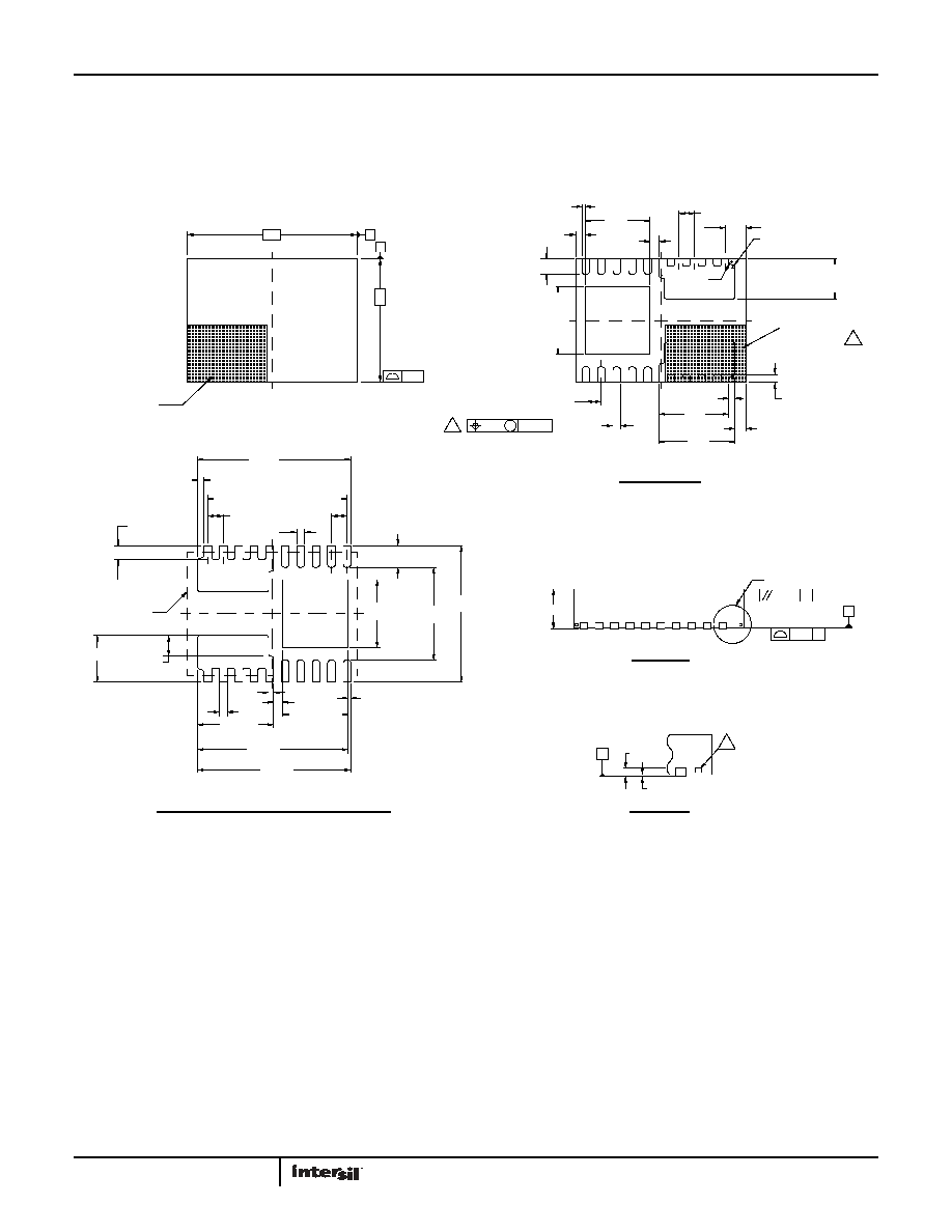
Package Outline Drawing
L20.5.5x4.0
20 LEAD DUAL FLAT NO-LEAD PLASTIC PACKAGE
Rev 2, 9/09
0.30
(2.20)
10X 0.70
2.10
2X 1.50
(4.95)
10 X 0.25
2X 2.45
PACKAGE
10X 0.45
(4.40)
(3.0)
(4.85)
(4.95)
10X 0.50
(4.50 )
10X 0.25
(2X 0.20)
(0.10)
0.16
0.68
BOTTOM VIEW
DETAIL "X"
SIDE VIEW
TYPICAL RECOMMENDED LAND PATTERN
TOP VIEW
Dimensions in (
) for Reference Only.
Tiebar shown (if present) is a non-functional feature.
between 0.015mm and 0.30mm from the terminal tip.
Unless otherwise specified, tolerance : Decimal ± 0.05
Dimensioning and tolerancing conform to AMSEY14.5m-1994.
located within the zone indicated. The pin #1 indentifier may be
The configuration of the pin #1 identifier is optional, but must be
Dimension applies to the metallized terminal and is measured
either a mold or mark feature.
6.
5.
Dimensions are in millimeters.
4.
3.
2.
1.
Angular ±2°
7. No other electrical connection allowed under backside of X1 or X2 areas.
NOTES:
SEATING PLANE
0.08 C
0.10 C
2X1.30
0.300
0.30
0.66
5.5
A
4.0
B
2X
0.10
PIN 1
INDEX AREA
0.35
R0.0750
10X 0.50
0.20
2.25
2.45
2.20
2.10
18X 0.50
C
0.2 REF
0-0.05
1.30
5
SEE DETAIL "X"
C
6
A
0.10M CB
4
0.10
1
10
11
20
10X 0.25
10 x 0.25
10 X 0.50
PIN #1
BOUNDARY
INDEX AREA
8. Soldering required to PCB for X1 and X2 pads to separate and
non-connected metal pads.
发布紧急采购,3分钟左右您将得到回复。
相关PDF资料
ISL12022IBZ-T7A
IC RTC/CALENDAR TEMP SNSR 8SOIC
ISL12022MAIBZ
IC RTC/CALENDAR TEMP SNSR 20SOIC
ISL12022MIBZ-T7A
IC RTC/CALENDAR TEMP SNSR 20SOIC
ISL12022MIBZR5421
IC RTC/CALENDAR TEMP SNSR 20SOIC
ISL12023IVZ
IC RTC/CLDR TEMP SNSR 14-TSSOP
ISL12024IRTCZ
IC RTC/CALENDER 64BIT 8-TDFN
ISL12024IVZ
IC RTC/CALENDAR EEPROM 8-TSSOP
ISL12025IVZ
IC RTC/CALENDAR EEPROM 8-TSSOP
相关代理商/技术参数
ISL12021
制造商:INTERSIL 制造商全称:Intersil Corporation 功能描述:Real Time Clock with On Chip Temp Compensation 【5ppm
ISL12021CVZ
功能描述:IC RTC LP BATT BACK SRAM 14TSSOP RoHS:是 类别:集成电路 (IC) >> 时钟/计时 - 实时时钟 系列:- 产品培训模块:Obsolescence Mitigation Program 标准包装:1 系列:- 类型:时钟/日历 特点:警报器,闰年,SRAM 存储容量:- 时间格式:HH:MM:SS(12/24 小时) 数据格式:YY-MM-DD-dd 接口:SPI 电源电压:2 V ~ 5.5 V 电压 - 电源,电池:- 工作温度:-40°C ~ 85°C 安装类型:表面贴装 封装/外壳:8-WDFN 裸露焊盘 供应商设备封装:8-TDFN EP 包装:管件
ISL12021IVZ
制造商:INTERSIL 制造商全称:Intersil Corporation 功能描述:Real Time Clock with On Chip Temp Compensation 【5ppm
ISL12022
制造商:INTERSIL 制造商全称:Intersil Corporation 功能描述:Real Time Clock with On Chip ±5ppm Temp Compensation
ISL12022IBZ
功能描述:实时时钟 REAL TIME CLK/CLNDR W/TEMP COMP 8 L RoHS:否 制造商:Microchip Technology 功能:Clock, Calendar. Alarm RTC 总线接口:I2C 日期格式:DW:DM:M:Y 时间格式:HH:MM:SS RTC 存储容量:64 B 电源电压-最大:5.5 V 电源电压-最小:1.8 V 最大工作温度:+ 85 C 最小工作温度: 安装风格:Through Hole 封装 / 箱体:PDIP-8 封装:Tube
ISL12022IBZ-T
功能描述:实时时钟 REAL TIME CLK/CLNDR W/TEMP COMP 8 L RoHS:否 制造商:Microchip Technology 功能:Clock, Calendar. Alarm RTC 总线接口:I2C 日期格式:DW:DM:M:Y 时间格式:HH:MM:SS RTC 存储容量:64 B 电源电压-最大:5.5 V 电源电压-最小:1.8 V 最大工作温度:+ 85 C 最小工作温度: 安装风格:Through Hole 封装 / 箱体:PDIP-8 封装:Tube
ISL12022IBZ-T7A
功能描述:实时时钟 REAL TIME CLK/CLNDR W/TEMP COMP 8 L RoHS:否 制造商:Microchip Technology 功能:Clock, Calendar. Alarm RTC 总线接口:I2C 日期格式:DW:DM:M:Y 时间格式:HH:MM:SS RTC 存储容量:64 B 电源电压-最大:5.5 V 电源电压-最小:1.8 V 最大工作温度:+ 85 C 最小工作温度: 安装风格:Through Hole 封装 / 箱体:PDIP-8 封装:Tube
ISL12022M
制造商:INTERSIL 制造商全称:Intersil Corporation 功能描述:Low Power RTC with Battery Backed SRAM, Integrated ±5ppm Temperature Compensation, and Auto Daylight Saving